
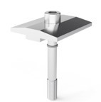

Mounting Systems centre clamp 30-40 mm; 40 mm (natural aluminium)
No longer available
Product information
The Mounting Systems centre clamp is a universal connecting element for safely securing two adjacent solar modules to a substructure. This version is designed as a universal clamp and flexibly covers module frame heights from 30 to 40 mm. The specification "40 mm" refers to the width of the clamping surface, which ensures optimal load distribution on the frame edges.
Thanks to the variable clamping range, the component automatically adapts to the respective frame thickness when tightened. This reduces complexity in material planning, as only one type of clamp is needed for various module generations.
Highlights at a glance
- Flexible clamping range: Suitable for solar modules with frame heights between 30 mm and 40 mm.
- Wide contact surface: The 40 mm wide clamping jaw ensures a stable hold and prevents damage to the module frame by localised pressure.
- High corrosion resistance: Made from high-quality aluminium and stainless steel screws for long-lasting resistance to weathering.
- Efficient installation: Allows simultaneous fixing of two modules with only one fixing point, reducing installation time per kilowatt-peak ($kWp$).
- Universal compatibility: Precisely fits common Mounting Systems profile systems as well as many cross-brand aluminium mounting rails.
- Symmetrical load distribution: The design ensures uniform contact pressure on both adjacent module frames.
Areas of application
The centre clamp is used within a module field for connection:
- Photovoltaic rooftop systems
- Standard fixing for pitched roof systems to securely connect rows of modules together.
- Commercial PV systems
- Used in large projects where the speed and reliability of components are critical.
- Multi-row module fields
- Wherever more than one module per rail row is installed and a defined space (module gap) is required between the units.
Installation & safety instructions
- Centring
- The centre clamp must be positioned exactly between the two module frames. Make sure that both frames are covered evenly by the clamp.
- Tightening torque
- Tighten the stainless steel screw to the recommended torque (usually 8–10 Nm). Too little tightening jeopardises storm resistance, too much tightening can deform the frame.
- Earthing / potential equalisation
- Observe the applicable regulations regarding earthing of the mounting system. Some centre clamps feature integrated earthing pins that pierce the anodised coating of the frame.
Properties
| Category | Centre clamp natural aluminium |
|---|---|
| Clamping range (frame height) | 30 – 40 mm |
| Material | Aluminium (high-quality anodised/natural) |
| Colour / Finish | Natural aluminium (silver) |
| Clamp length | 40 mm |
| Area of application | Connection between two solar modules |
| Compatibility | Mounting Systems rail profiles |
| Mounting method | Click or screw fixing |
| Weather resistance | Very high / corrosion-resistant |
FAQs on the Mounting Systems centre clamp
Can I use this clamp for any solar module?
Yes, provided the frame height is in the range of 30–40 mm.
- Most modern high-performance modules have frame thicknesses of 30 mm, 35 mm or 40 mm, making this clamp almost universally applicable.
Is the distance between the modules specified by the clamp?
Yes.
- The centre bar of the clamp creates a technical gap between the modules (usually approx. 20 mm). This gap is necessary for the thermal expansion of the rails and modules.
Is the clamp supplied complete with sliding block?
Usually, yes.
- The clamp is usually supplied as a set including screw and sliding block or click block. Check in advance if the block is compatible with your specific rail profile groove.
Is this model also available for black module frames?
Yes.
- For an aesthetically pleasing installation of full-black modules, this clamp is also available in a black anodised version available.
Login
Customers also bought
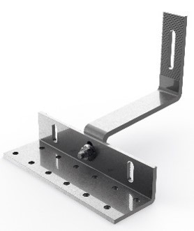
The Mounting Systems roof hook 170-7-40 is a high-quality and flexible fastening solution for photovoltaic systems on tiled roofs. Thanks to its 2-way adjustability it can be optimally adapted to different batten thicknesses and tile heights. This enables a tension-free installation of the substructure, even on uneven roof surfaces or with varying roof tile formats.Manufactured from robust stainless steel, this roof hook provides extremely high corrosion resistance and mechanical strength. It forms the stable foundation for the connection between the rafters and the mounting rails of your PV system.Highlights at a glanceMaximum flexibility: The 2-way adjustability allows the height under the cantilever (to the roof batten) as well as the vertical adjustment of the mounting rail.High-quality material: Manufactured from stainless steel (1.4301), which guarantees decades of durability and protection against the elements.High load capacity: The material thickness of 7 mm ensures superior stability and safety against high wind and snow loads.Optimum dimensions: With a base plate of 170 mm length, the hook offers a generous contact surface for secure screw fastening on the rafter.Time-saving installation: The slotted hole version on the cantilever allows tolerances to be easily compensated when installing the rails.Universally applicable: Suitable for most common kinds of pantile (e.g. Frankfurter Pfanne, Erlus, Braas).Areas of ApplicationThe roof hook is the ideal choice for demanding pitched roof installations:PV systems on tiled roofsSecure anchoring of the substructure directly into the rafter on standard coverings.Compensation for roof unevennessThanks to the adjustment option, “waves” in the roof can be compensated to achieve a visually perfect, flat module field.Regions with high loadsThanks to the solid 7 mm construction, it is particularly suitable for areas with increased structural requirements.Installation & Safety InstructionsProfessional screw connectionFasten the roof hook with at least two suitable pan head screws (stainless steel) directly into the rafter. Make sure the required screw-in depth is achieved.Tile recessThe overlying tile must be professionally worked with an angle grinder (flex) at the point where the hook emerges to avoid "tile breakage" due to direct contact.Maintain spacingEnsure that a gap of approx. 5 mm is maintained between the roof hook and the tile below to prevent load transfer to the tile. Properties CategoryRoof hook 170-7-40 Adjustability2-way adjustable Material thickness7 mm MaterialStainless steel (highly corrosion-resistant) Cantilever height40 mm (basic dimension) Base plate width170 mm Area of applicationTiled roofs (Frankfurter Pfanne and similar) Type of fasteningRafter mounting using wood screws Weather resistanceVery high / maintenance-free FAQs about the Mounting Systems roof hook 170-7-40Why is an adjustable roof hook better than a fixed one?Flexibility with the roof batten.Since roof battens can vary in thickness (e.g. 30 mm or 40 mm), this hook can be adjusted so that it does not rest on the lower tile and at the same time does not lift the upper tile.Does this hook fit all mounting rails?Yes, when using M10 hammer head screws.Using the slotted hole at the upper end of the hook, almost all standard aluminium profiles can be securely fastened with an M10 screw and locking nut.How many roof hooks do I need per module?Depending on statics.On average, around 2 to 2.5 roof hooks per module are calculated. In snowy areas or on the roof edge (wind load), however, the number may be significantly higher.Do I always have to flex the tiles?Yes, with standard pantiles.To ensure that the tiles lie flat again after installation and are not stressed by the hook, it is absolutely necessary to machine the tiles.
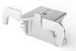
The Mounting Systems FD3 module support (front) is a central component of the FD3 flat roof system. This system is specially designed for ballast-optimised installation of photovoltaic systems on flat roofs with low load reserves. The front module support forms the low fixed point of the substructure and largely determines the angle of inclination of the solar modules.Made from high-quality, corrosion-resistant aluminium, the module support ensures a durable and secure connection between the floor rail and the front edge of the solar module. The aerodynamic design of the FD3 system minimises wind lift, significantly reducing the need for heavy ballast.Highlights at a glanceOptimised aerodynamics: Part of the overall FD3 system, which has been tested in a wind tunnel to ensure maximum stability with minimum counterweight.High material quality: Made of weather-resistant aluminium, ensuring a long service life without corrosion risk.Quick assembly: Thanks to pre-assembled components and simple screw connections, the front support can quickly be fixed to the floor rails.Precise inclination: In combination with the rear module support, a fixed installation angle (mainly 10° or 15°) is achieved for optimal yield.Protection of the roof covering: The system is installed without roof penetration; the module support distributes the loads evenly across the floor rails.Module-friendly fixation: The contact surfaces are designed so that the frames of the solar modules are securely held without causing mechanical stress.Areas of applicationThe FD3 module support front is the basic component for flat roof installations:Commercial flat roofsIdeal for large industrial halls with trapezoidal sheet metal or foil sealing, where the total weight of the system matters.Private houses with flat roofsSimple and visually discreet elevation for garages, carports or bungalows.East-west or south orientationThe module support can be flexibly used in various FD3 configurations, both for classical south-facing systems and roof area-optimised east-west systems.Installation & safety instructionsSystem networkThe front module support may only be used in combination with the original FD3 floor rails and the corresponding connectors to avoid jeopardising the structural approval.BallastingEnsure that the ballast required according to the structural plan (e.g., concrete blocks) is correctly placed on the rails, as the module support itself weighs nothing.Maintain distancesEnsure correct row distances during installation to prevent mutual shading of the modules. Properties CategoryFD3 module support front System compatibilityMounting Systems FD3 (flat roof) PositioningFront / Low side of the elevation MaterialHigh-strength aluminium / Stainless steel components Area of applicationFlat roof solar systems (Ballasted or Bolted) Installation methodModule clamping on FD3 substructure Weather resistanceVery high / Corrosion-resistant according to industry standard FunctionSecure anchoring of the module frame at the front Maintenance requirementMaintenance-free FAQs on the FD3 module support frontCan I adjust the angle of inclination flexibly?No.With the FD3 system, the inclination angle is determined by the fixed heights of the front and rear module supports (10° as standard). This provides high stability and easy wind load planning.Is the mounting material for fixing to the module included?Usually separate.The module support is attached to the floor rail. For securing the solar modules to the support, the appropriate centre and end clamps are required, which are matched to the frame height of your modules.Do I need protective mats?Yes, strongly recommended.To protect the roof membrane or bitumen sheet from mechanical damage by the floor rails, suitable protective mats (PADs) should always be placed under the system's contact points.How many front supports do I need?One support per module support point.Usually each module requires two support points at the front. Depending on the rail layout, one FD3 module support front is mounted per support point.
